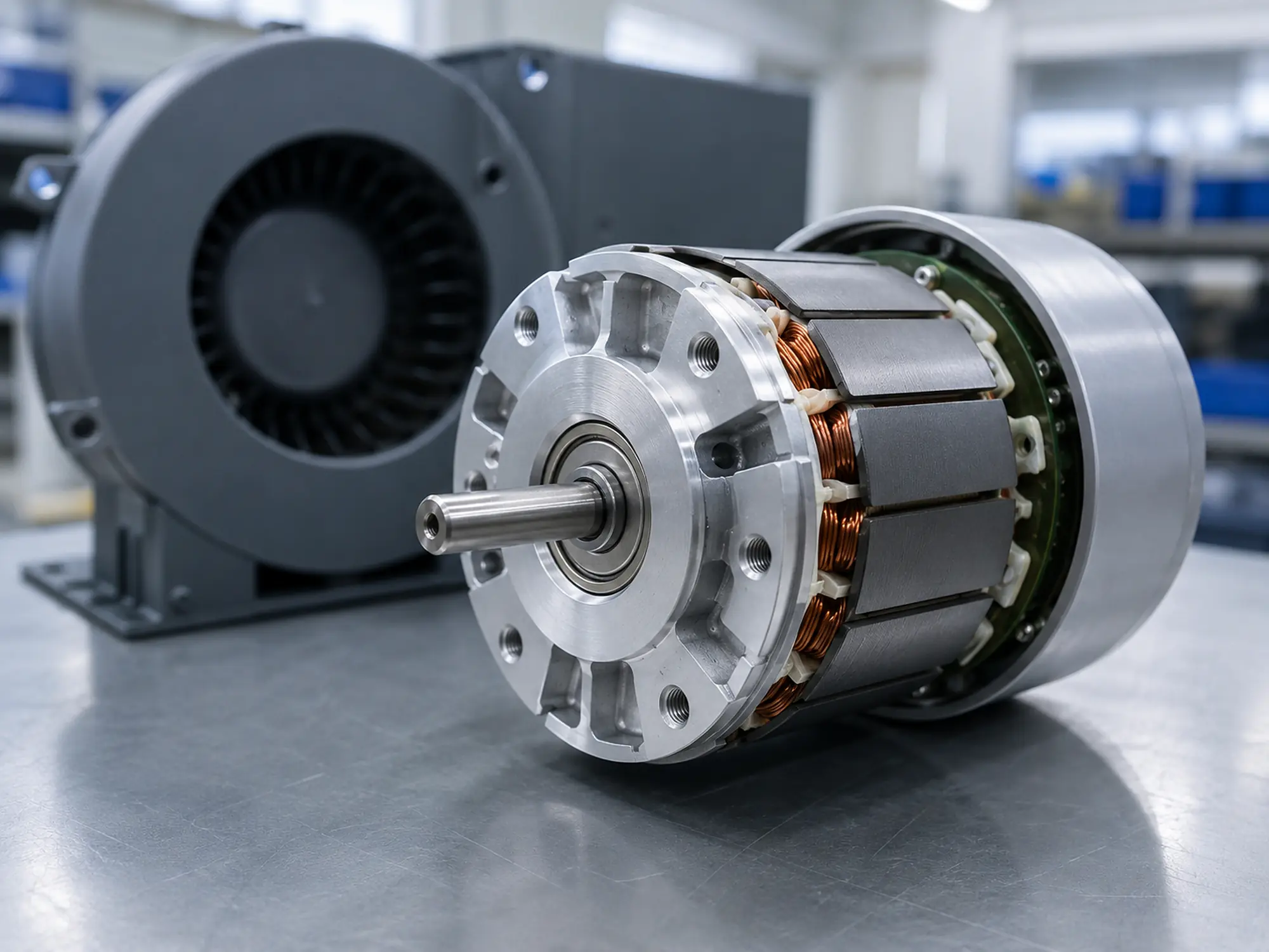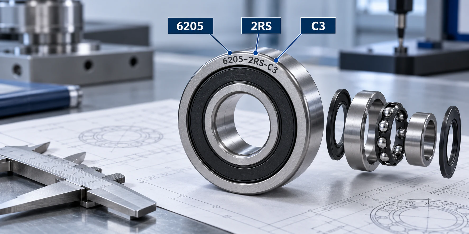
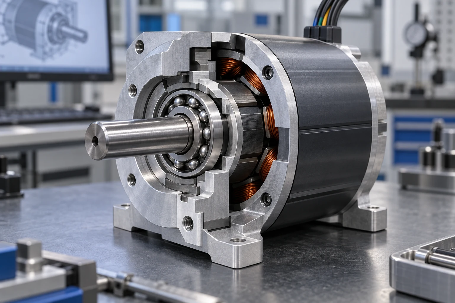
An OEM may ask whether a small motor needs CN or C3 bearings, but the suffix is not the first design decision. A bearing is supplied with an initial internal clearance. Once its rings are fitted to the shaft and housing, and once the motor reaches operating temperature, the effective clearance can be different. The correct choice therefore depends on the complete assembly.
That does not mean C3 is a universal motor upgrade, or that CN is automatically the quieter option. Either choice can be unsuitable when the shaft, housing, load direction, materials, tolerances, temperature, speed, and mounting process are not defined. The defensible task is to predict and then validate the mounted and operating condition.
Separate three clearance conditions
Initial internal clearance
Initial clearance is the condition of the unmounted bearing under the specified measurement method. It gives the supplier and OEM a controlled starting point, but it does not by itself describe the condition inside the completed motor.
The RFQ should identify the required bearing designation, clearance class, measurement basis, and any application-specific range only after engineering has considered the assembly. If the project needs measured values rather than a class label, define how the records will be linked to the supplied lot.
Mounted clearance
Mounting can change the relationship between the rings and rolling elements. An interference fit on a shaft or in a housing can change ring geometry and reduce available clearance. The amount depends on the actual dimensions, tolerances, materials, wall thickness, surface condition, and assembly state—not only the nominal bearing size.
NSK's engineering reference explains that fits and internal clearance materially affect performance. It also warns that unsuitable interference can be associated with creep, cracking, clearance loss, heat, or seizure. This supports reviewing fit and clearance together instead of selecting them as independent catalogue fields.
Operating clearance
The motor's warm condition introduces another change. The inner ring, outer ring, shaft, housing, end shields, and nearby heat sources may not reach the same temperature or expand in the same way. The resulting operating clearance must still support the intended load, noise, torque, temperature, and life-related requirements.
Do not replace thermal analysis with a generic “motors run hot” assumption. Record the locations and conditions under which temperatures are measured, including ambient, electrical load, duty cycle, speed, cooling, orientation, and warm-up time.
Define which ring sees rotating load
Fit selection begins with how each ring moves relative to the load direction. A small motor often has a rotating shaft, but that fact alone does not completely define the ring-load relationship. Imbalance, belt or gear force, fan load, magnetic force, axial loading, housing motion, and the operating orientation may affect the load case.
Document the force direction and which ring experiences a load that rotates relative to it. Also record shock, vibration, start-stop behavior, reversals, and whether the motor is transported while assembled. These conditions help the responsible engineer decide where creep resistance is needed and what fit strategy should be evaluated.
The Engineering Stack Exchange question retained in the research evidence shows the practical difficulty of turning a rotating-ring concept into shaft and housing drawing dimensions. It also raises the difference between an aluminum housing and steel components. This is useful practitioner context: the final drawing needs dimensions and tolerances that the fabrication process can actually hold.
Put real tolerances on the drawing
Nominal dimensions do not define a fit. Engineering should specify the shaft and housing tolerance zones or explicit limits, the applicable temperature basis, the surface finish and form expectations, the datum strategy, and how the dimensions will be measured. A fit decision based on one nominal diameter can hide the actual interference range.
Review both tolerance extremes. The loosest combination must still resist unwanted ring movement where required. The tightest combination must not create an excessive mounted condition. For thin housings, lightweight end shields, or unusual shaft materials, the surrounding component may respond differently from a rigid catalogue assumption.
Manufacturing capability matters as well. A design that requires a tolerance the supplier or fabrication shop cannot measure or hold consistently will produce variable assemblies. Confirm measurement equipment, sampling, process capability expectations, and the reaction plan before approving volume production.
Include material and geometry in the fit review
The material names “steel” and “aluminum” are not enough for a final calculation. The engineer needs the actual component material, geometry, wall thickness, support condition, temperature range, and relevant material data. Hollow shafts, thin housings, split housings, polymer carriers, adhesive retention, and press-fit sequence may require a different analysis.
Surface condition and geometry also matter. Check roundness, cylindricity, taper, shoulders, fillets, burrs, cleanliness, and whether the mounting tool contacts the correct ring. A correct tolerance callout cannot compensate for a tilted bearing or an assembly force transmitted through the rolling elements.
Connect clearance to motor behavior
The chosen operating condition must be validated against what matters in the motor. Depending on the project, measure starting and running current, torque, noise, vibration, shaft runout, axial movement, temperature, speed stability, and functional performance under the actual load and duty cycle.
Too little effective clearance may be associated with higher friction, heat, or an unsuitable internal load. Too much effective clearance may affect shaft control, noise, vibration, or load distribution. These are engineering relationships to evaluate, not universal pass/fail diagnoses. Other problems—lubricant, contamination, rotor balance, alignment, electrical excitation, or assembly damage—can produce similar symptoms.
Build a paired sample validation
A controlled comparison should hold constant the bearing geometry, supplier, lubricant, closures, motor components, assembly process, and measurement method wherever possible. If CN and C3 variants are compared, document actual shaft and housing measurements for every sample rather than relying only on drawing targets.
Use production-intent assemblies and traceable bearings. Record the initial bearing evidence, component dimensions, press data where available, baseline motor measurements, and warm-run results at defined checkpoints. If the project measures mounted clearance directly, define the method and its uncertainty. If it uses functional indicators, state clearly that those indicators do not measure clearance by themselves.
The sample quantity, load, speed, temperature, duty cycle, test duration, and acceptance limits must come from the application risk and engineering plan. This guide does not provide a universal clearance range or motor temperature limit.
RFQ checklist before naming CN or C3
Send the bearing supplier and application engineer:
- bearing designation, arrangement, and required life-related or performance targets;
- shaft and housing nominal dimensions, tolerances, materials, geometry, and surface conditions;
- which ring rotates relative to the load and the radial, axial, shock, and vibration conditions;
- motor speed, duty cycle, ambient, internal temperatures, cooling, and warm-up profile;
- lubricant, closures, preload or axial-location method, and mounting sequence;
- noise, vibration, torque, current, runout, and temperature measurement methods;
- sample plan, traceability, acceptance limits, and change-notification requirements.
FAQ
Is C3 always better for an electric motor?
No. A larger initial-clearance class may be appropriate in some fitted and thermal conditions, but the correct choice depends on the complete bearing arrangement and operating requirements.
Can the bearing supplier choose clearance from the shaft diameter alone?
No. Housing fit, tolerance ranges, materials, load direction, component geometry, temperature, speed, lubricant, and motor requirements also matter.
Does an interference fit always reduce internal clearance by the same amount?
No. The result depends on actual interference, ring and surrounding-component geometry and materials, surface condition, and assembly behavior. Project-specific analysis is required.
Can noise testing prove the clearance is correct?
Noise testing can help validate the assembled motor, but it does not isolate clearance from lubrication, contamination, balance, alignment, electrical sources, or assembly damage.
What should be controlled after approval?
Control the bearing clearance class or agreed range, shaft and housing drawings, materials, critical dimensions, lubricant, closures, mounting method, test method, traceability, and relevant supplier or process changes.
Evidence record and engineering limits
- NSK Global — Fits and Internal Clearance supports reviewing fit, interference, load direction, tolerance, temperature, and clearance as connected decisions. It does not prescribe a CN or C3 answer for a LUMI motor project.
- Engineering Stack Exchange — How to specify bearing clearance fit provides public practitioner context about converting ring-load and material assumptions into manufacturable shaft and housing dimensions. It is not a controlled design standard.
Prepare the fit-and-clearance boundary for LUMI
LUMI can review a miniature or small deep-groove bearing only against the actual motor assembly. Share the bearing arrangement, load direction, shaft and housing drawings and materials, dimensional results, speed, duty cycle, temperature measurements, lubricant, closures, mounting process, and acceptance method. See the miniature bearing range, electric-motor selection guide, application context, and quality process, then use the project inquiry form for an engineering review.