Shaft fit
Select shaft tolerance from load direction, rotating ring and accuracy requirement. Installation force must act on the ring being fitted.

F / MF SERIES · METRIC FLANGED BEARINGS
A flanged ball bearing adds a radial flange to one side of the outer ring. The flange seats against a housing or plate face and establishes the outer ring's axial position during assembly.
The flange is a mounting feature, not a load-capacity upgrade. Shaft fit, housing fit, axial retention, closure and operating conditions still need to be specified for the complete assembly.
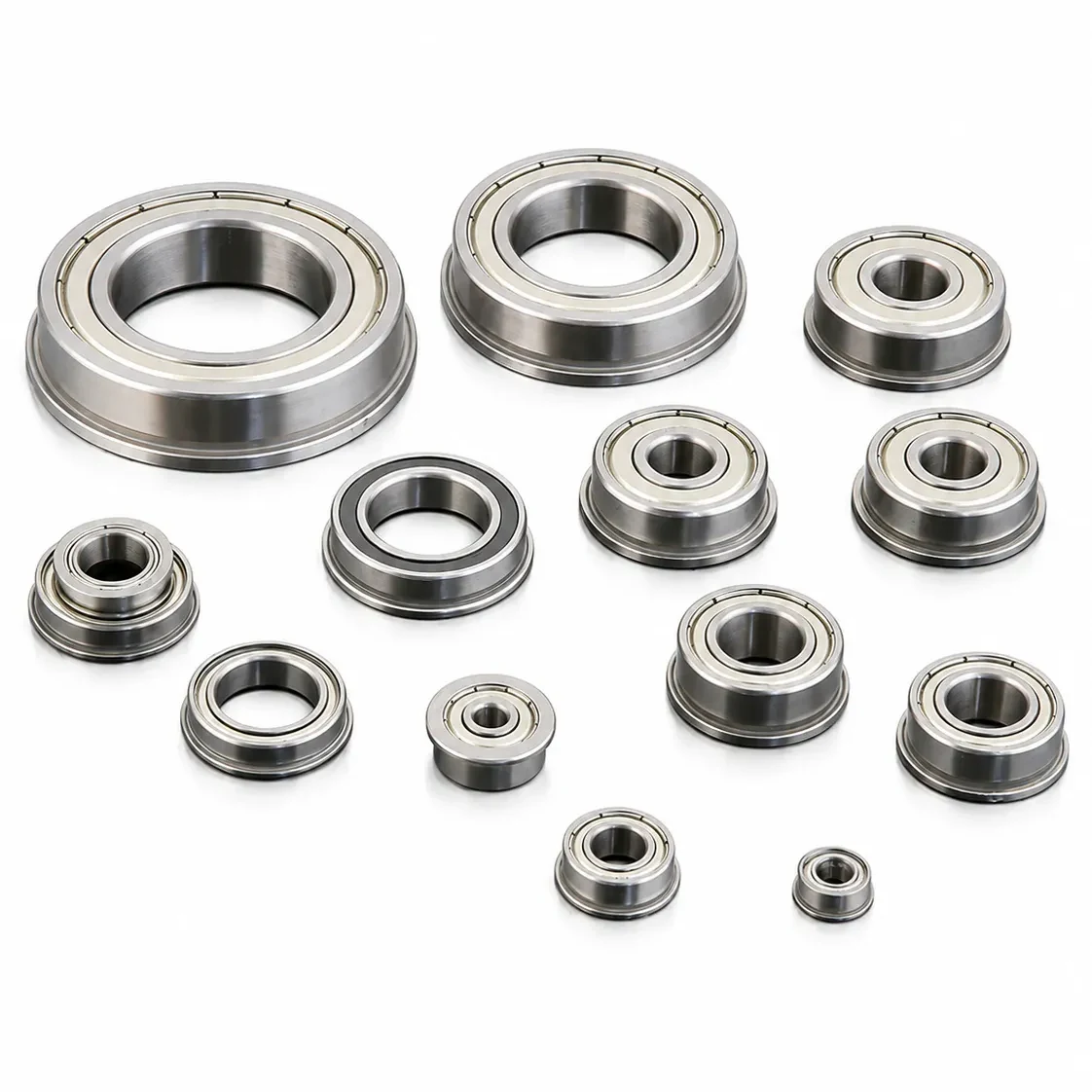 Integrated outer-ring flange
Catalogue size checking
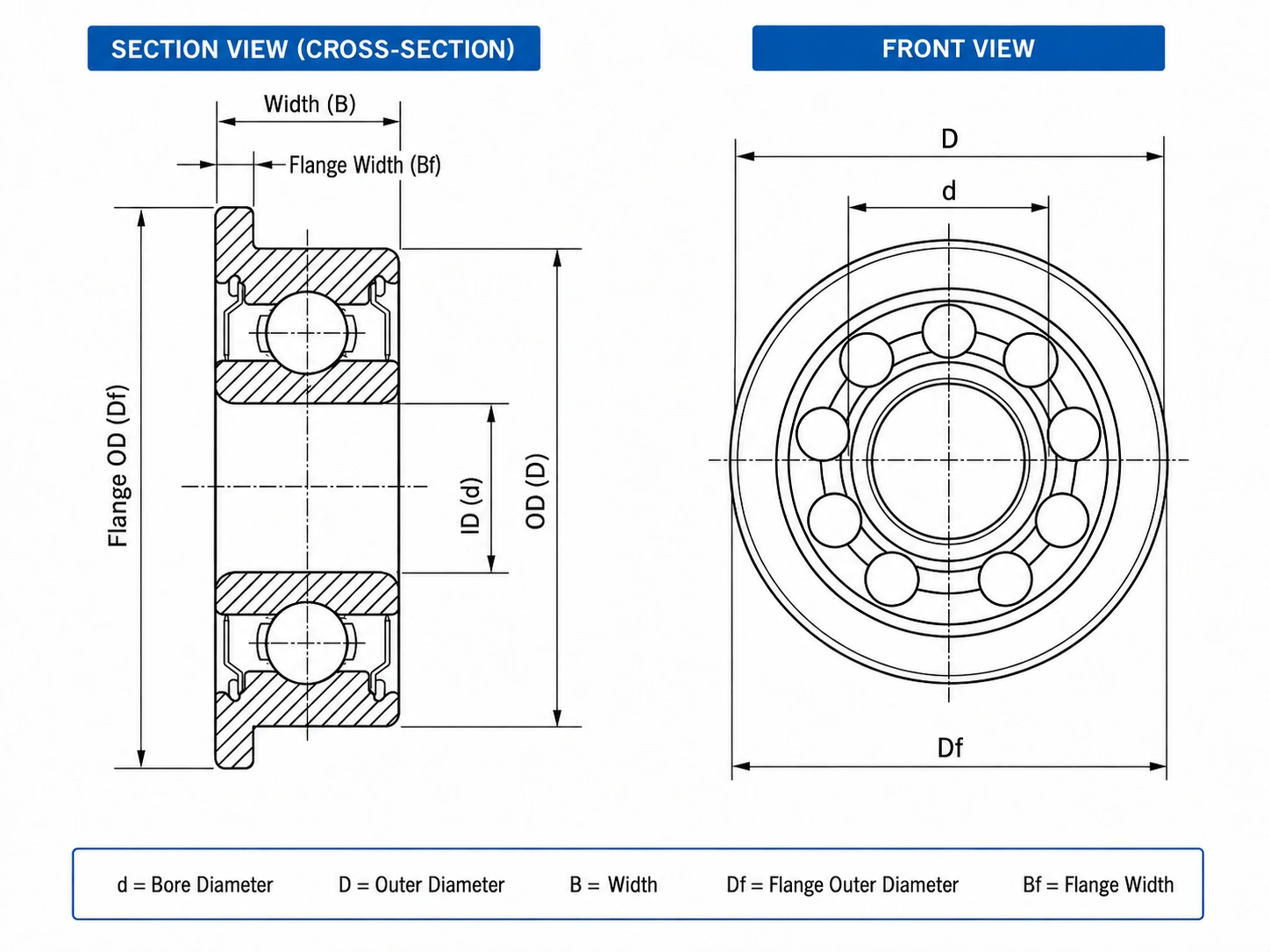
Browse all entries directly or narrow the table by model and dimensions. Df and Bf define the flange envelope.
74 catalogue entries shown
Df and Bf are flange dimensions| Model | dmm | Dmm | Bmm | Dfmm | Bfmm | Closure | DynamicN | StaticN | Speedrpm | RFQ |
|---|---|---|---|---|---|---|---|---|---|---|
| F681 | 1 | 3 | 1 | 3.8 | 0.3 | Open | 80 | 23 | 130000 | RFQ |
| F691 | 1 | 4 | 1.6 | 5 | 0.5 | Open | 138 | 35 | 100000 | RFQ |
| MF41X | 1.2 | 4 | 1.8 | 4.8 | 0.4 | Open | 138 | 35 | 110000 | RFQ |
| F681X | 1.5 | 4 | 1.2 | 5 | 0.4 | Open | 112 | 33 | 100000 | RFQ |
| F681XZZ | 1.5 | 4 | 2 | 5 | 0.6 | ZZ | 112 | 33 | 100000 | RFQ |
| F691X | 1.5 | 5 | 2 | 6.5 | 0.6 | Open | 237 | 69 | 85000 | RFQ |
| F691XZZ | 1.5 | 5 | 2.6 | 6.5 | 0.6 | ZZ | 237 | 69 | 85000 | RFQ |
| F601X | 1.5 | 6 | 2.5 | 7.5 | 0.6 | Open | 330 | 98 | 75000 | RFQ |
| F601XZZ | 1.5 | 6 | 3 | 7.5 | 0.8 | ZZ | 330 | 98 | 75000 | RFQ |
| F682 | 2 | 5 | 1.5 | 6.1 | 0.5 | Open | 169 | 50 | 85000 | RFQ |
| F682ZZ | 2 | 5 | 2.3 | 6.1 | 0.6 | ZZ | 169 | 50 | 85000 | RFQ |
| MF52B | 2 | 5 | 2 | 6.2 | 0.6 | Open | 187 | 58 | 85000 | RFQ |
| MF52BZZ | 2 | 5 | 2.5 | 6.2 | 0.6 | ZZ | 187 | 58 | 85000 | RFQ |
| F692 | 2 | 6 | 2.3 | 7.5 | 0.6 | Open | 330 | 98 | 75000 | RFQ |
| F692ZZ | 2 | 6 | 3 | 7.5 | 0.8 | ZZ | 330 | 98 | 75000 | RFQ |
| MF62 | 2 | 6 | 2.5 | 7.2 | 0.6 | Open | 330 | 98 | 75000 | RFQ |
| MF72 | 2 | 7 | 2.5 | 8.2 | 0.6 | Open | 385 | 127 | 63000 | RFQ |
| MF72ZZ | 2 | 7 | 3 | 8.2 | 0.6 | ZZ | 385 | 127 | 63000 | RFQ |
| F602 | 2 | 7 | 2.8 | 8.5 | 0.7 | Open | 385 | 127 | 63000 | RFQ |
| F602ZZ | 2 | 7 | 3.5 | 8.5 | 0.9 | ZZ | 385 | 127 | 63000 | RFQ |
| F682X | 2.5 | 6 | 1.8 | 7.1 | 0.5 | Open | 208 | 74 | 71000 | RFQ |
| F682XZZ | 2.5 | 6 | 2.6 | 7.1 | 0.8 | ZZ | 208 | 74 | 71000 | RFQ |
| F692X | 2.5 | 7 | 2.5 | 8.5 | 0.7 | Open | 385 | 127 | 63000 | RFQ |
| F692XZZ | 2.5 | 7 | 3.5 | 8.5 | 0.9 | ZZ | 385 | 127 | 63000 | RFQ |
| MF82X | 2.5 | 8 | 2.5 | 9.2 | 0.6 | Open | 560 | 179 | 60000 | RFQ |
Showing 1–25 of 74 models
Outer-ring structure
The flange is a radial lip formed on one side of the outer ring. When it seats against a flat housing or plate face, it creates an axial datum for the outer ring without requiring a full internal shoulder behind the bearing.
The flange stops the outer ring in one axial direction and makes the installed position repeatable. This is useful when the seat is a thin plate, compact end bracket or shallow housing.
Where the load path and assembly allow it, the flange can remove the need for an additional shoulder, circlip groove or separate retaining washer on the locating side.
Rated load comes from the bearing's internal geometry, materials and size. Adding a flange does not by itself raise dynamic or static load capacity.
The flange does not replace the correct shaft fit, housing fit or a retention method for the opposite axial direction. Those choices must follow the load direction, rotation and assembly stack-up.
Housing and shaft interface
d, D and B define the bearing envelope; Df and Bf define the flange seat and adjacent-part clearance.
Select shaft tolerance from load direction, rotating ring and accuracy requirement. Installation force must act on the ring being fitted.
Control the housing bore so the outer ring is supported without interference that removes required internal clearance.
Seat the flange against a clean, square face and define how the bearing is retained in the opposite axial direction.
Provide clearance around Df and at the flange root; a cover or housing edge must not bear on an unintended surface.
Do not transmit fitting force through the balls. Press the inner ring for a shaft fit and the outer ring for a housing fit.
Mounting comparison
The choice follows the housing geometry and locating method; neither structure is universally better.
| Selection point | Standard Ball Bearing | Flanged Ball Bearing |
|---|---|---|
| Outer ring structure | Cylindrical outside surface | Integrated flange on one side of the outer ring |
| Axial positioning | Uses a shoulder, cover, circlip or separate locating feature | Flange provides a locating face in one axial direction |
| Housing design | Usually provides the locating geometry around the outer ring | Can reduce the need for a full internal shoulder or separate retainer |
| Installation | Position follows the surrounding housing features | Df, Bf and the flange seating face join d × D × B in the fit review |
| Available space | Works where conventional retention fits the envelope | Useful where housing depth or locating hardware is constrained |
| Typical applications | Motors, gear stages and instruments with conventional seats | Encoders, compact motors and mechanisms needing a positive locating face |
Catalogue families
F and MF prefixes cover different metric flange constructions. Confirm the complete d, D, B, Df and Bf values rather than treating a similar bore or prefix as interchangeable.
Protection and running behaviour
All three examples below are flanged bearings. Confirm exact suffix, width and speed for the selected model.
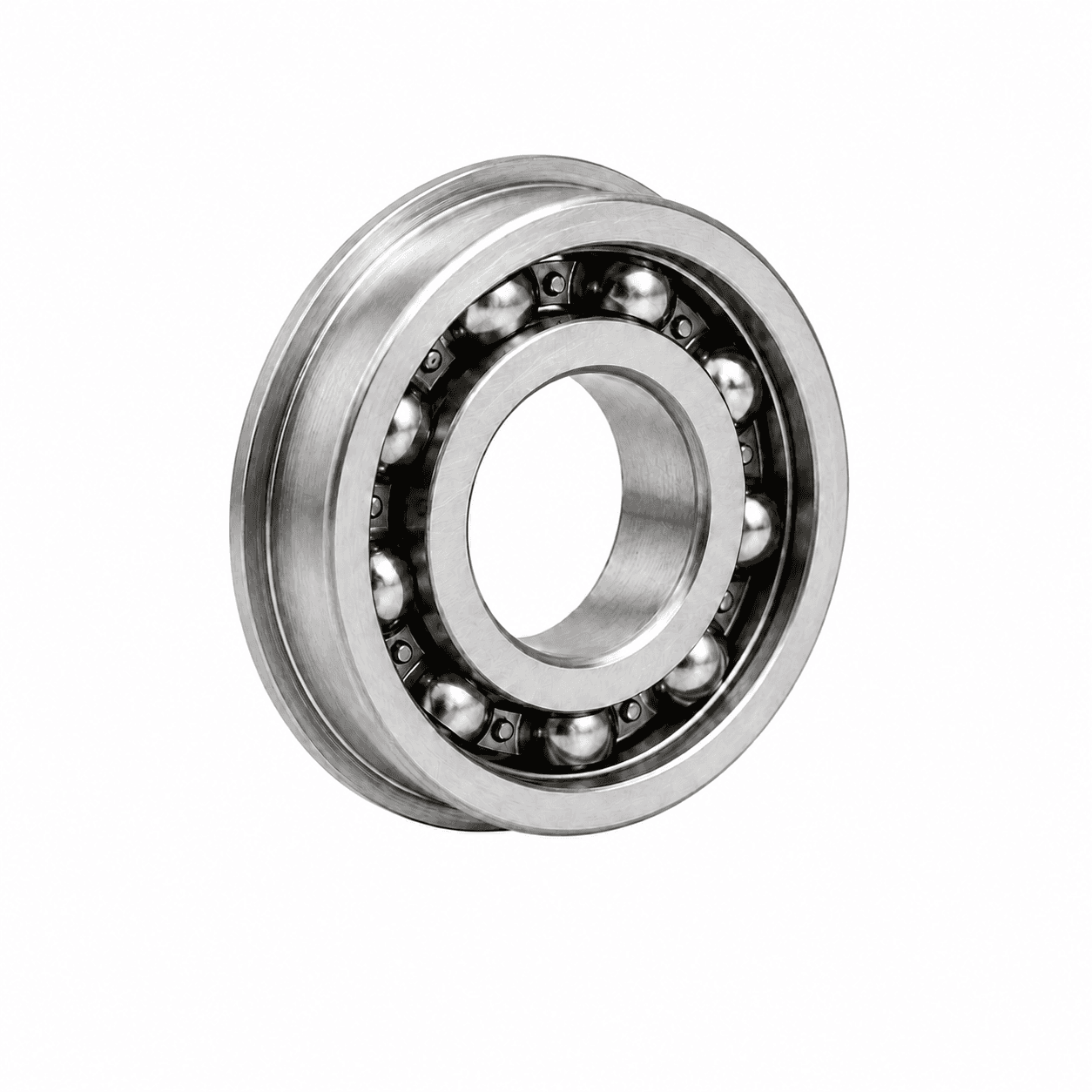
Used in clean, controlled mechanisms where direct lubricant access or the absence of closure drag is required.
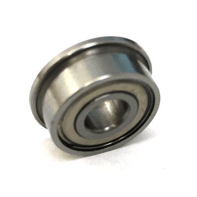
Helps retain grease and exclude larger particles with less closure drag than a contact rubber seal.
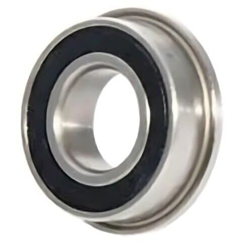
Provides stronger dust and moisture exclusion where the added seal torque and lower permissible speed are acceptable.
Closure availability, bearing width, load rating and limiting speed are model- and manufacturer-specific. Confirm the final suffix and drawing before ordering.
Material availability is confirmed by model. Select the material system around corrosion exposure, load, wear, speed, operating environment and project cost.
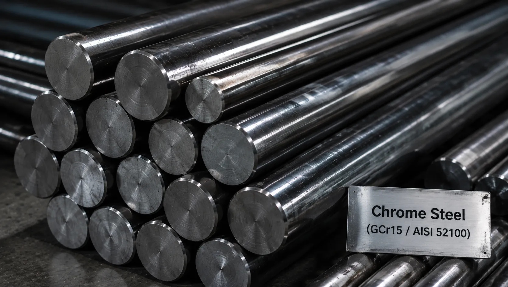
A common material system for motors, gearboxes and general industrial applications where corrosion resistance is not the primary requirement.
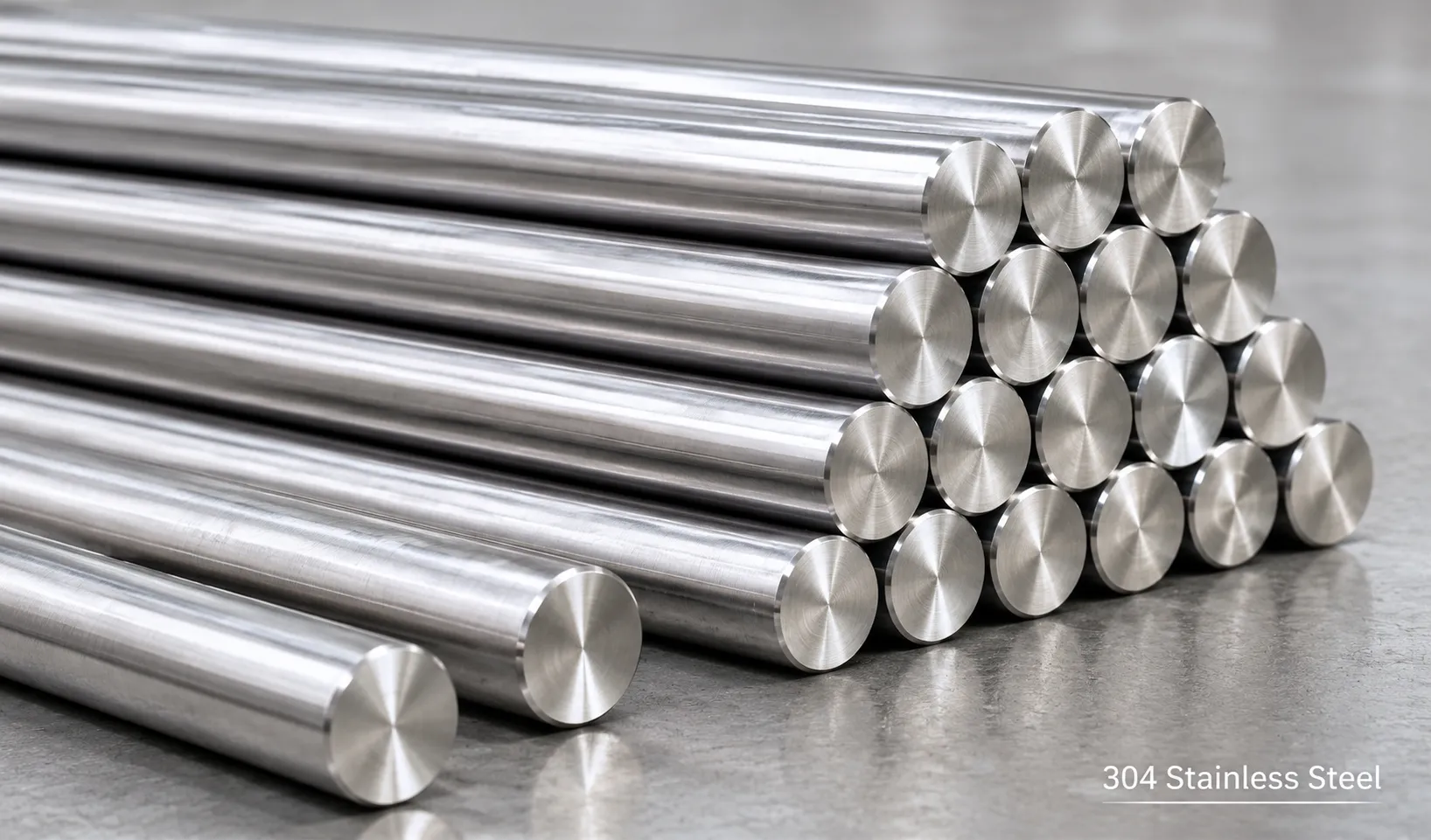
Strong corrosion resistance for humid or corrosion-sensitive environments; mechanical and load requirements must be considered for the application.
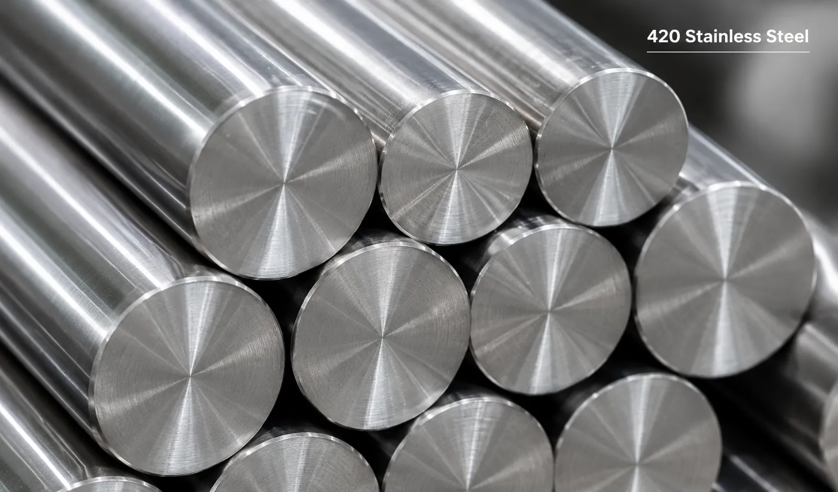
A balance of hardness, wear resistance and corrosion resistance for bearing applications that also require mechanical strength.
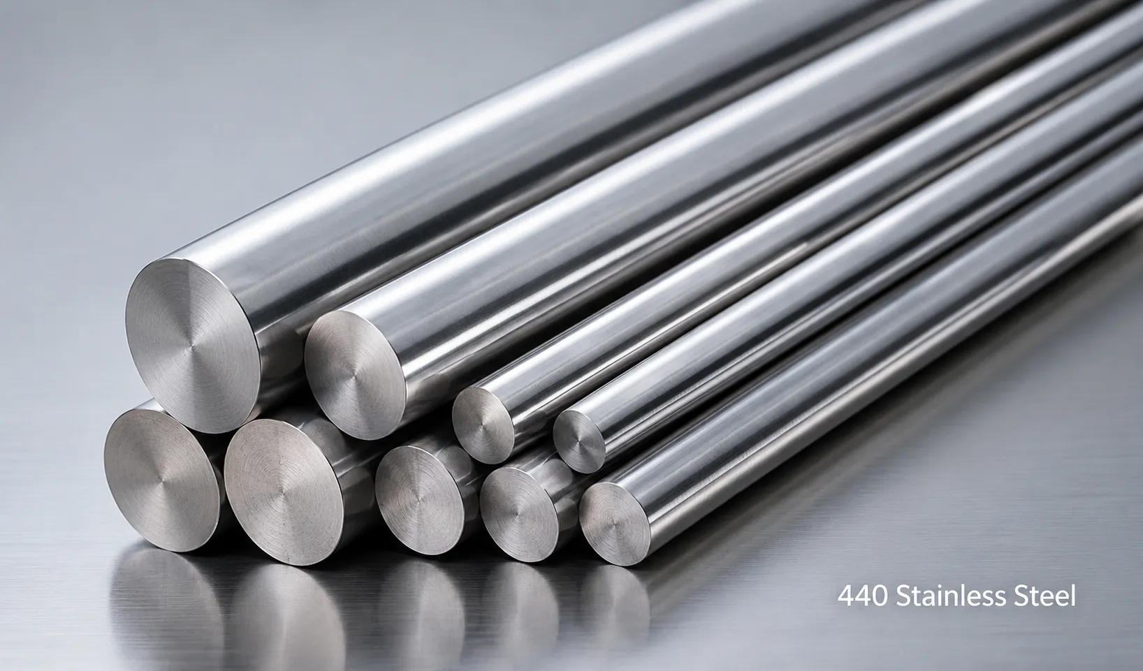
Higher hardness and wear resistance for precision stainless bearing applications requiring stronger bearing performance.
Compare the complete operating requirement rather than selecting from corrosion resistance or hardness alone.
Mounting reasons by assembly
Each example focuses on the locating or housing constraint that leads to a flanged construction.
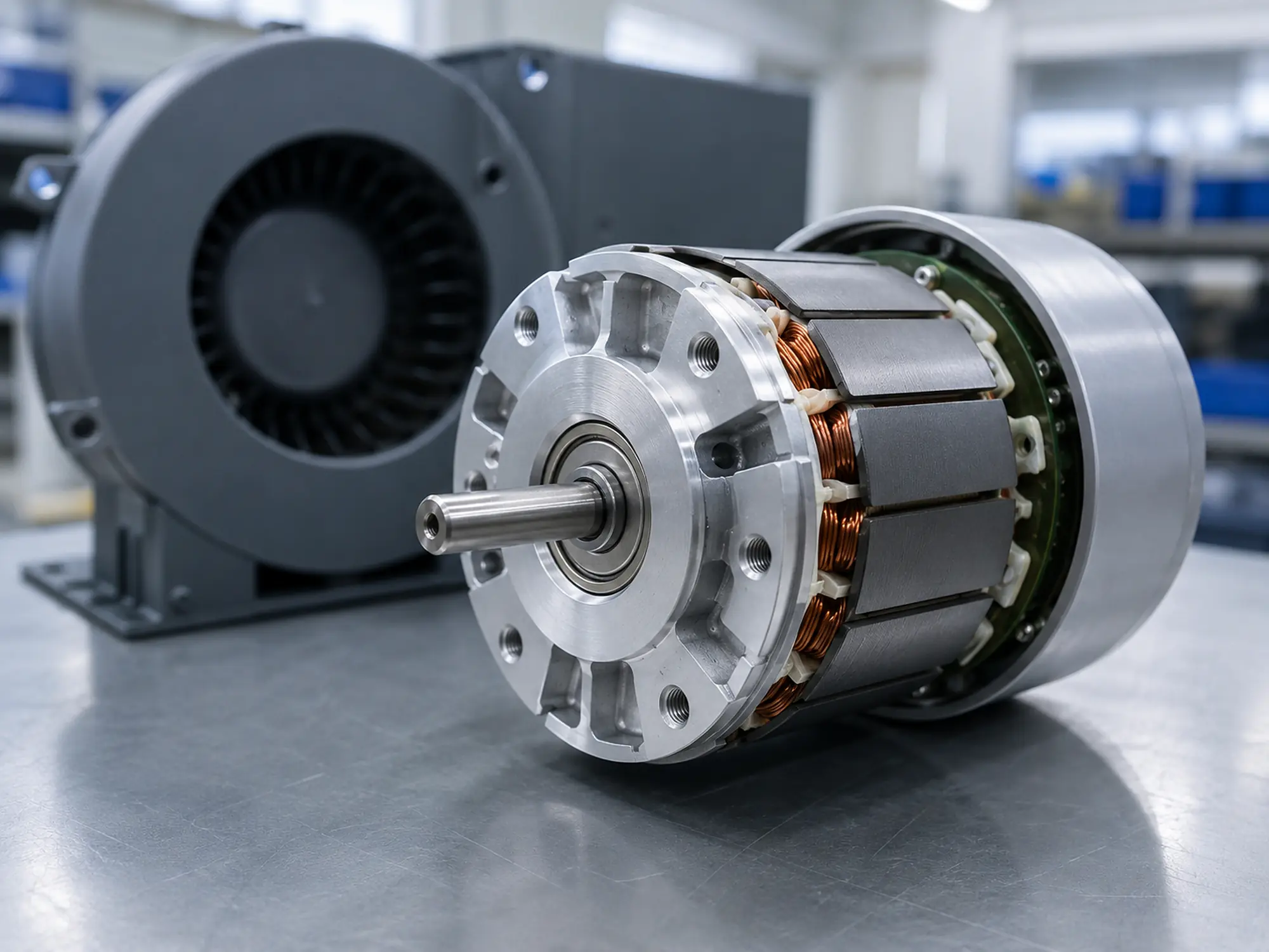
The flange can locate the outer ring against a thin end bracket where machining a full internal shoulder would consume axial space.
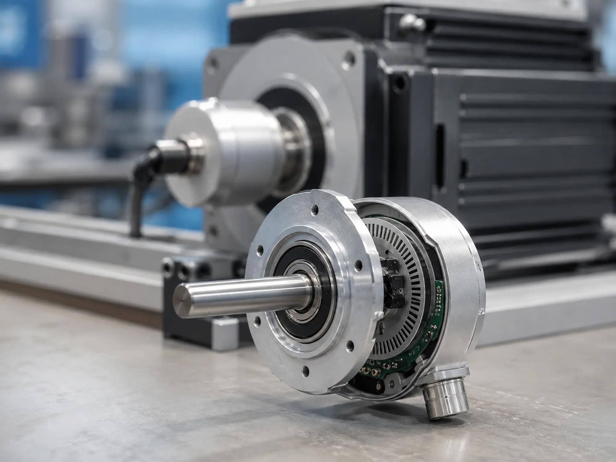
A defined flange face provides a repeatable axial datum between the bearing, shaft and sensing components.
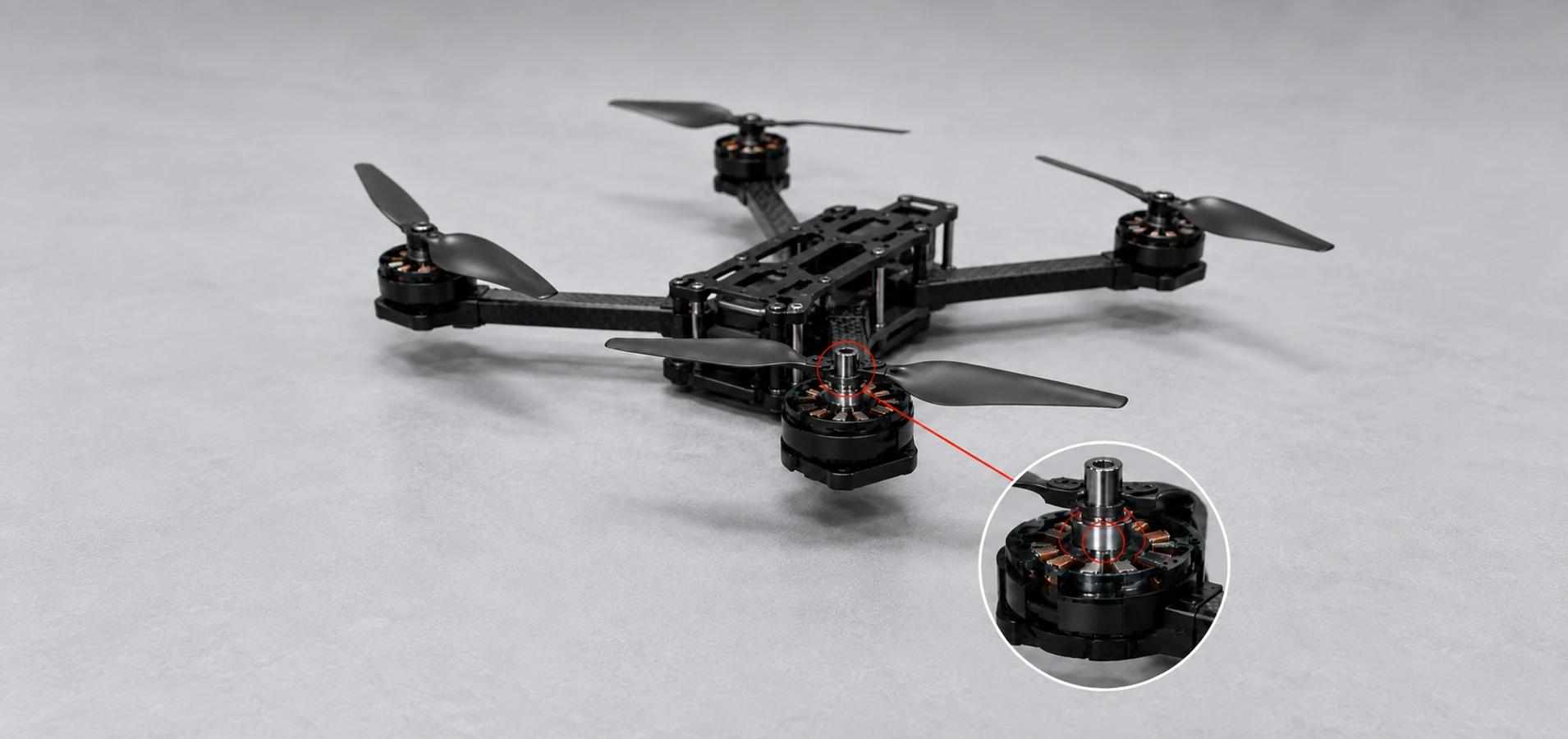
Compact joint housings can use the flange as a locating stop while keeping the bearing seat short.
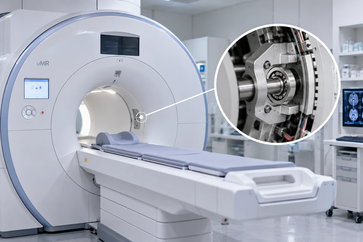
The flange helps position small rotating parts where housing depth and assembly datum are tightly controlled.
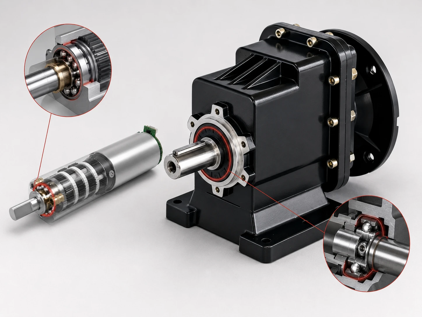
A flange can reduce the need for an additional shoulder or retaining plate around a small gear shaft.
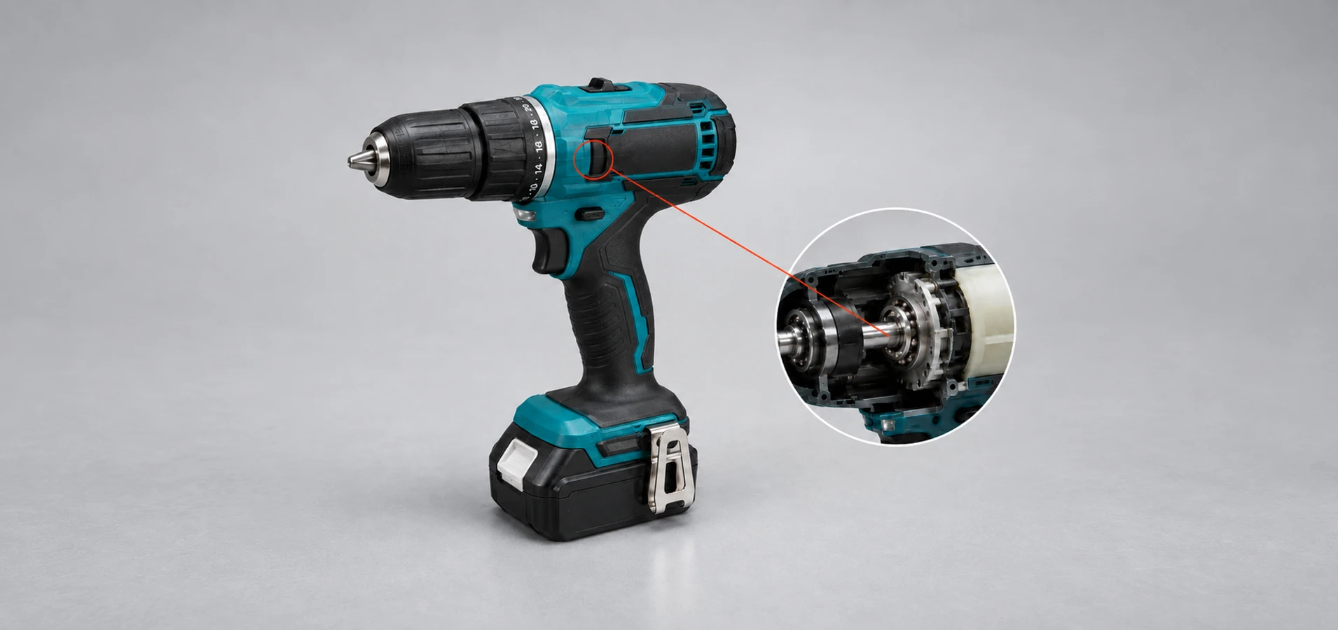
The outer-ring flange provides a positive locating surface when a separate circlip or machined shoulder is impractical.
Selection workflow
Complete the geometry and fit checks before deciding closure or material.
Start with shaft nominal size, tolerance, rotation and load direction.
Check the housing bore and the outer-ring fit required for the duty.
Verify available axial space and the complete shaft stack-up.
Confirm flange outside clearance, seating-face diameter, thickness and adjacent-part clearance.
Choose open, ZZ or 2RS from contamination, grease retention, torque and speed.
Review load, speed, lubrication, temperature, noise and expected duty.
Engineering / OEM support
Include the bearing envelope, flange seat and operating conditions so the complete mounting arrangement can be reviewed.
Send RequirementsCheck d × D × B and Df × Bf against the housing section, locating face and adjacent-part clearance.
Compare applied load and speed with catalogue ratings while accounting for fit, temperature, lubricant and duty cycle.
Align model, closure, material, clearance, grease and inspection points before sample approval.
Record the approved drawing, suffix, lubricant and inspection scope for repeat orders.

YOUR DIRECT CONTACT
For general questions, business support, early-stage communication, or a quick follow-up.
Inquiry & quick contact
Quality & inspection
Technical answers
It is a ball bearing with a radial flange formed on one side of the outer ring. The flange seats against a housing or plate face to locate the outer ring axially.
Provide the model or d × D × B, Df × Bf and operating conditions. LUMI can review the mounting arrangement and confirm the available specification.